Interface Cables
This section contains information on cables for Yaesu and Icom radios.
For other radios, contact a dealer for information on available cables. Information on building cables for other radios may be added in the future.
For Yeasu and Icom radios, here are the options: - Purchase a commercially available interface cable
- Build you own interface cable
- Use a cable you already own for another radio (many cables are the same or very similar).
Here are the basic cable setups for the different radios:Remember, you can use a USB to TTL cable in place of the RS-232 to TTL cable. (see below)
Purchasing Cables
Visit www.ttl2usb.com to purchase a high-quality USB cable that will work with ALL of my software!
You can also purchase cables from RT Systems
If anyone has a programming cable source they would like to recommend, let me know.
Building Cables
***** WARNING: Use of the software and information on this site is at your OWN RISK!!! *****
All links are provided for reference purposes only. Please don't attempt to build your own cable if you don't know what you're doing, you could damage your radio, your PC, or both. If you would like to build a cable but don't have the experience, try finding another ham in your area who has the experience and would be willing to help you build and test your cable.
There are many different variations of TTL to RS232 interface designs out there.I'll break them down into 3 main categories:
Six-Transistor Designs
I believe this is the same circuit that you get in commercial cables from RT Systems. This is a good choice for a circuit to build, since these cables seem to be solid performers.
Two-Transistor Designs
I think most of these are derivatives of the Icom OPC-478 design. These circuits are fairly simple and don't use a lot of parts. But, some people have had problems getting these designs to work, which might be the reason for so many variations. In some cases, Yaesu radios put too much of a "load" on the circuit, requiring additional buffering on the radio side.
MAX232/233 Designs
These are based on the MAX232/233 family of RS-232 Driver/Receiver ICs made by Maxim. Interface cables based on these ICs are a very good choice in my opinion, as they are more RS232 compliant than the transistor-based designs. They run on +5v, and contain a voltage doubler and a voltage inverter to produce proper signal levels of +10 and -10 volts respectively. The first two designs are the best choices for the Yaesu radios, since they have additional buffereing on the radio side, which is often required for proper operation.
MOSFET Interface
Dale (N�XAS) has designed an interface utilizing MOSFETs instead of transistors, greatly reducing the parts count.
USB Interface
Alexander Meier (DG6RBP) has designed a USB interface for Yaesu Radios, which was published in the german ham radio magazine CQ-DL. He sent me an english translation, complete with description, schematic, board layout, parts list etc.
Download the PDF Here.
Big thanks to Alexander for his unique project!
Pinouts
Here is the pinout of the 4-conductor plug for the VX-2R, VX-5R, and VX-7R.
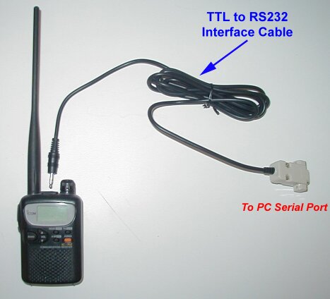
Here is the pinout of the 3-conductor plug for the VR-120 and the IC-R2.
Parts Sources
Sources for the 1/8" 4-conductor plug
Another effective but less elegant solution is not often mentioned, but it does work (at your own risk). Use a regular 1/8" 3-conductor stereo plug instead, which are readily available at Radio Shack and many other sources . The 4-conductor and 3-conductor plugs are the exact same length. When using the 3 conductor plug instead of the 4-conductor, two of the contacts in the jack will be shorted together when the plug is inserted. This has the effect of grounding the external microphone line for "Push To Talk" causing the radio to transmit. Simply remember to tune the radio to a frequency on which it isn't able to transmit before inserting the plug, and you are in business.
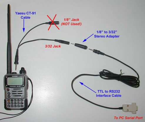
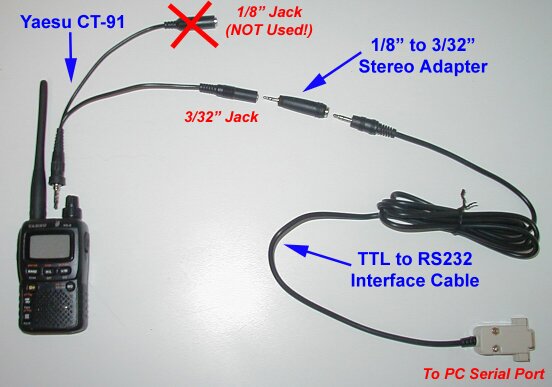
The VX-7R has a special recessed jack, and these plugs will not fit into the jack properly without grinding away some of the plug. Dan's Yaesu Modification Website has some more details on this procedure. Some people have had a difficult time getting this right. If in doubt, just buy the Yaesu CT-91.
Another solution for a cable that connects directly to the VX-7R is to buy a CT-91 and cut the cable to connect it to your interface.
Tip: If you don't like screwing and unscrewing the CT-91 every time you want to program your VX-7R, get an additional CT-91 and grind off the threads.
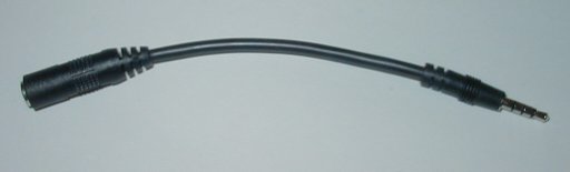
Sources for the 1/8" to 3/32" adapter (to connect to the 3/32" jack of the CT-91)
In the US, you can get this at your local Radio Shack, Part #274-373. These are likely available at most major retailers of audio components, and should not be too difficult to find.
Troubleshooting Your Cable
If your cable doesn't work with the Commander software, and you are positive that everything is connected properly and firmly:
Download my Interface Cable Loopback Tester and follow the directions to test your cable.
If your cable DOES NOT pass this test, there is a 99% chance there a problem with the cable and it won't work with any of the Commander software. Other rare possibilities include a hardware problem with the serial port, or a problem with Windows/drivers.
If your cable DOES pass the test, but still doesn't work to program the radio, it is likely that the radio loads the interface too much for proper operation. If this is the case, you should either add buffering to your circuit on the radio side (look at other designs), or choose a different design. But before breaking out the soldering iron, here are a couple of things to try that might make a difference:- Try it on another PC. If you are using a laptop, try it on a desktop.
- If the interface is homemade, try using external power instead of "port power".
My first cable was an ICOM OPC-478 based design, using two transistors. For me, it works fine on my VX-2, VX-7, VR-120, IC-Q7, IC-R2, on a friends VX-5, and works on every PC I have tried it on. But, many others have reported problems getting the design to work for them on their PCs/Radios because of loading issues.
The fact is, that NONE of the popular transistor-based cables properly implement RS-232, since they don't generate negative voltage, nor do they generate highs above 5v. Technically, lows should be between -5 and -15, and highs should be between +5 and +15. With these transistor cables, best case scenario is usually a low of 0v and a high of +5v.
Another thing that causes problems is the fact that most of these cables are "port powered", and slight differences in serial port voltage levels can make a difference, especially since the transistor-based designs do not use proper voltage levels for the signals in the first place. Serial ports were never designed to power external devices, although people have been doing this for a long time with varying success. Since these circuits were designed for signals, not to support a load, the voltage drops very fast when a load is connected, as they can supply little current.
Some laptop serial ports only go to +5 and -5 to save battery power. These signal levels may not be high enough for the PC to be able to send data to the radio through the interface.
There may be other subtle differences in COM port hardware, and it is possible that varying component tolerances used in the interface cables could cause problems too.
Jim Mitchell
KC8UNJ